Symptoms
- The analyzer reading is offset from the process reading by a consistent amount.
- The analyzer reading is frozen on one value.
- The analyzer reading is off the scale either up or down.
Diagnosis
You may have a ground loop. A ground loop is defined as “two or more electrically grounded points at different potentials.” More than one conductive path between ground terminals on the sensor and controller will create a ground loop. These conductive paths act like an antenna that picks up interference easily. The larger the loop, the more interference that is “measured” by the controller. The controller uses the signals it receives. If it receives a noisy signal, it will multiply errors, displaying erroneous or offset readings and outputs. (Garbage In-Garbage Out.)
A second possibility is that there may be no ground in the system. Check wiring connections.
A third possibilty is that there may be voltage/noise in the process introduced from another device.
Common Causes of a Ground Loops
Is the pH Controller connected to other components? Dataloggers or computers, connected to non-isolated analog outputs of the pH controller, may cause a problem. Wiring shields may be connected improperly. Moisture or corrosion in a junction box can also cause ground loops. Ground loops are usually attributed to the process or installation, rather than a fault in the instrumentation. Once the sensor is taken out of the process, the problem disappears – because the process or installation is providing the interference!
Systematic Troubleshooting of Ground Loops
1. Confirm There Is A Ground Loop.
- First, verify that the system measures buffers correctly, outside of the process.
- Next, create an electrical connection between the buffer cup and the liquid process. This can be done by connecting a heavy gauge wire to the process piping, or place the wire in the process tank. Place the other end of the test wire into the buffer cup with the pH sensor. If similar symptoms develop in the buffer cup, as were seen in the process, then the ground loop is confirmed. If no symptoms develop, then the ground loop is not confirmed, but it does not rule one out.
2. Verify Process Grounding.
- The pH electrode system needs one path to ground; and, that path is through the process. Plastic piping, fiberglass tanks, ungrounded, or poorly grounded, vessels do not provide this path. The system is therefore floating and is highly susceptible to any noise from mixers, pumps, motors, etc.
- Ground the piping or tank to earth ground. Metal flow-thru tees, ground rings, or grounding rods may be required.
- If ground loop symptoms persist, connect a wire from GROUND at the DC Power Source to the transmitter’s case. Connect another wire from the transmitter’s case to the process. These connections force all of the grounds to the same potential.
- If the problem persists, simple grounding is not the problem. There must be noise interference getting into the instrument. Try simplifying the pH sensor wiring, to reduce the possible noise paths.
3. Simplify the pH Sensor Wiring.
- Retain the following sensor wire connections at the transmitter (if wired directly), or at the input side of the remote preamplifier if one is used: RTD SNS, RTD IN, REF IN, pH/ORP IN.
- Remove the extra sensor wires. Tape the ends to keep them from shorting out.
- Connect a jumper wire between temperature compensation input terminals (usually RTD’s).
- Connect an additional jumper wire between the Reference Input and Solution Ground terminals.
- Ensure that the sensor shields and inner drain wires do not touch grounded metal (insulate them to protect from contact with ground).
- Place the pH sensor back into the process. If the display is free of diagnostic messages, determine if the ground loop symptoms have been eliminated.
- Interpret Test Results. If the ground loop is gone, then the interference must have been coming into the instrument on one of the disconnected wires. The pH system can successfully operate with the simplified wiring on a permanent basis.

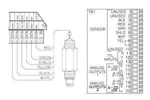
Examples of pH Sensor Input Wiring Sequences
4. Disable Instrument Nuisance Alarms.
- Many analyzers have built-in diagnostics that may actually interfere with the troubleshooting process. Consult the instrument’s instruction manual for steps about temporarily disabling these warnings.
Extra Ground Connections or Induced Noise
A ground loop exists when a circuit is connected to earth ground at two or more points. The potential of the earth varies from point to point, so multiple connections to ground cause currents to flow. If the current flows through a signal wire, the result is a noisy, offset signal.
The pH electrode system is connected through the liquid process to earth ground. If the circuitry in the pH transmitter becomes connected to a second earth ground, current will flow through the reference electrode. If an extra earth ground connection is made, multiple electrical paths are created. Ground loop symptoms are observed.
Offset & Noisy Readings Electrically, it looks like this: A voltage, proportional to the current and the electrode resistance, develops across the reference electrode. Because the voltage is in series with the other potentials in the sensor cell, the ground loop current causes the pH reading to be substantially different, offset from the expected value. pH readings affected by ground loops are often noisy as well.
Additional Options for Eliminating Ground Loops
Use shielded cables. Cable shielding prevents stray electrical fields from the surrounding area from riding along the signal wire into the controller. Ground the cable shield at one end only: the controller end. Some sensors have two “ground” wires. Connect the “shield ground” wire to the controller’s shield terminal. Connect the “ground” wire to the controller’s “ground” terminal.
The most common path for incoming interference is through the sensor cabling. The interference is either through a direct connection between grounded metal and one of the sensor leads or the noise (EMI/RFI) is being inducted into the cable. Try running the sensor cable outside of its metal conduit, if applicable, (a shield may be exposed and touching metal inside the conduit).
- Reinsert the sensor in the process. If the ground loop symptoms are eliminated, then the interference likely came from a short between the sensor cable and the metal conduit. Repair any bare spots on the cable. Carefully reinstall the cable in the conduit. If the interference still exists, then the noise is possibly being inducted into the cable or transmitter.
- To avoid induced noise in the sensor cable, re-route the pH sensor cable to avoid close proximity to power wires, motors, pumps, etc. Remove the sensor wiring from running through a crowded panel or move it outside of a cable tray. In rare instances, noise has been inducted into the transmitter’s metal housing by the metal that it is mounted on. The noise that gets into the transmitter’s metal housing will be radiated into the circuit boards. Try removing the transmitter housing from its metal mounting and isolate it. If this technique resolves the interference, then remount the transmitter in a different location, or mount it with isolating materials.
- The sensor should be grounded only to the controller. Do not ground a sensor to building steel or to the power system ground at the remote mounting point. Some installations will require that the controller housing have a safety ground. In this case, isolate the controller housing from the sensor. Ground each separately.
- In wiring sensor to dual-input analyzers, remember that ground wires from one sensor should not be shared with another. Prevent current “crosstalk” interference from one sensor to another by wiring the sensors separately to their specific controller input terminals.
New Problem On An Older System? Ask, “What changed in the process recently?” Retrace the steps taken in making the recent changes/updates that could have inadvertently introduced interference into the sensor-to-analyzer signal path. Were all of the wires reconnected to the correct terminals?
- Remember: Water conducts electricity. Check terminal connections for moisture. Take steps to insulate against leaks into the enclosure. Replace old gaskets and junction boxes as necessary.