My pH sensor is in a hot process, and the readings appear to be off. Do you have any suggestions?
We recently reviewed an application where this was the concern.
Here’s the application: Both tank and contents are hot.
Temperatures range: 140-160º F
The tank is filled with plant effluent. Its composition varies and could contain chemicals such as Phosphoric Acid and Caustic. It also contains entrained oil. The purpose of the system is to lower the effluent pH to 4.5 with Sulfuric Acid, breaking up the emulsion (oil). Next, the solution is raised to a neutral, 7 pH, by the addition of Caustic (50% NaOH).
Here are the steps that were taken to get the measurement on track:
Check the wiring. Clean the sensor. Calibrate the sensor. The operator performing a pH calibration must be patient during this process, as can take a while to get stable results.
1. Check the sensor wiring.
Confirm it to be correct, per the correct wiring diagram (instrument instruction manuals, websites, or tech support have this information.) Wiring must be correct for the system to function properly.
2. Calibrate the sensor. (3-Part Process)
-
Calibration Step 1: Cool the sensor.
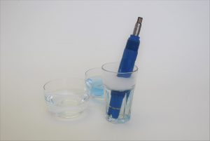
As pH readings are affected by temperature, pH readings are temperature compensated. There is a temperature element in the sensor that sends an output to the analyzer/transmitter. When removing the sensor from the process, the sensor should be set in tap water and allowed to cool to the same temperature as the buffers so as to not create an offset in the calibration. The entire thermal mass of the sensor needs to cool, as well as the temperature element inside the sensor. This will take some time – perhaps 15-30 minutes. The temperature needs to stabilize for the calibration to work. It should not be changing during the calibration process.
Tip: The higher the temperature of the process, the shorter the life span of any pH sensor.
Tip: A 5-degree difference from the buffer to sensor temp comp cause a big error in the pH slope.*
-
Calibration Step 2: Clean the sensor.
Next, the sensor should be carefully cleaned. Often this is done by soaking the sensor with glass submerged in a container of tap water at room temperature and a mild dish soap. Some operators will soak the sensors overnight. Read the recommended cleaning procedures in the sensor operation manual. Inspect the probe glass for any coating, grease, particulate. Examine the physical condition of the glass.
-
Calibration Step 3: Calibrate the sensor.
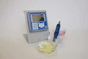
Opt for Manual Calibration. Many analyzers/transmitters allow the operator to select automatic or manual calibration. In the case of high temperatures, manual calibration is recommended.
Here’s why: software can often time-out, ending the calibration process. An operator can observe the conditions, allowing for changes in mV readings as the sensor temperature cools. This may take a bit longer than auto-calibration timers allow. So, use Manual Calibration — and be patient!
We recommend using both 4 and 7 buffers. 7 and 4 buffers are more stable than 10 buffers. Do not use 10 buffers. Follow the two-point calibration instructions in the analyzer/transmitter instruction manual.
*pH Slope
pH sensors generate a mV signal when placed in water. pH analyzers/transmitters read that signal calculate formulas and produce an output like a display, etc. One calculation is the slope number, which is used for comparison by the analyzer’s diagnostics as the pH sensor ages. Good working pH sensors should have a slope reading of -56 and -61 mV/pH value.
The ideal reading of a new sensor would be -60 mV/pH at 25°C is. For example, if the calibration slope is determined to be -58.5 at 25 o C it would equal 97.5% of the theoretical slope. This is good. How is slope calculated? If a pH electrode placed in 7 buffer reads 0.5 mV, and 180.5 mV in the 4 buffer, the slope is (0.5-180.5) mV/ (7-4)pH = -60 mV/pH.
In ideal conditions, a 7 pH buffer is 0 mV to a pH sensor. How far the output drifts from zero is an indicator of sensor life. This can be observed by placing a clean sensor in pH 7 buffer. One way to extend sensor life is to change the sensor’s reference junction. When the junction gets older, or fouled by the process, it needs to be replaced.


